home aircraft books history links old news quotes soft sounds weather
For flying something like a zagi,
you need to mix 2 controls together.
For up/down elevator (elevons move together) and left/right aileron (elevons
move opposite).
This can be done in the Tx if you have a computer version, or it can be done in
the aircraft, in line with the 2x signals from the Rx to the 2x servos.
I tend to use the computer Tx exclusively for powered aircraft, leaving the
older/cheaper challenger Tx for the gliders.
So all that need them have an onboard mixer.
I bought 2 kits for the Mk2 V tail mixer from
here. These went into the original
heavy zagiand siesta.
No source code provided, but a swift bit of reverse engineering allowed me to
emulate the behaviour.
The home made mixer went into the light zagi.
Note: there is little point in doing this again, as
commercially available units (kits and complete) are about the same cost, and
usually use surface mount devices, saving weight.
I mainly did it as an intellectual exercise, for fun.
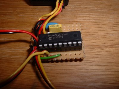
It uses a 16f84a pic on a bit of
veroboard, with just a 4M resonator and a decoupling capacitor. Measured weight
8g.
I hard wired the servos and power lead direct to the vero board to eliminate
the weight of the connectors.
Software developed and programmed into the device using the picstart plus development kit from microchip.
![]()
Source view and download.
;*******************************************************************
; mixer8.asm - came from mixer7.asm
; 2001/08/18
; measure the length of 2 input servo pulses
; generate 2 output mixed sum and difference pulses
;*******************************************************************
; rtcc not used - ideal resolution is 5us not a prescale option
; use instruction timing instead
; instructions take 1us or 2us for branch type
; count loop takes 5us
; mid pulse = 1.52ms = 304 loops = 0x130h (256 + 48)
; desired count for mid pulse is 0 so
; preload counter with 0 - 0x30h = 0xd0h (208)
; can't tell which will come 1st so need to check both
;*******************************************************************
;
         LIST    p=16F84A               ; PIC16F84A is the target processor
        #include "P16F84A.INC"          ; Include header file

; defines to find things easier
; ***** pic register equates *****
rtcc    equ     1                       ; counter register
pc      equ     2                       ; program counter
status  equ     3                       ; status register
carry   equ     0                       ; carry bit
zro     equ     2                       ; zero bit (note spelling)

; ***** port assignments *****
porta      equ        5                          ; port a equates
portb      equ        6                          ; port b equates
ip0        equ        0                          ; input 0
ip1        equ        1                          ; input 1
opsum      equ        2                          ; sum output to servo
opdif      equ        3                          ; dif output to servo
lo0        equ        0ch                        ; use 1st spare register as lo byte counter
hi0        equ        0dh                        ; use 2nd spare register as hi byte counter
lo1        equ        0eh                        ; use 3rd spare register as lo byte counter
hi1        equ        0fh                        ; use 4th spare register as hi byte counter
sum        equ        10h                        ; for sum op pulse timing
dif        equ        11h                        ; for dif op pulse timing
pulse      equ        12h                        ; counter for op pulse timing
;
        org   0                                  ; reset vector
        goto    init                             ; start at init
; init **************************************************************
init    movlw   b'00000011'             ; set a0-a1 inputs
        tris    porta                   ;     a2-a3 outputs
        clrf    porta                   ; clear porta out bits
        movlw   0h                      ; set port b as all outs
        tris    portb
        movlw   b'00000010'             ; rtcc pre-scalar /8
        option                          ; 8us count loop = 2.048ms

        movlw        b'01010101'                ; alternate bits set
        movwf        portb                      ; put the count out to port b
        movlw        0h                         ; 0
        movwf        lo0                        ; init counters to 0
        movwf        hi0                        ;
        movwf        lo1                        ;
        movwf        hi1                        ;

; ***********************************************************
; wait for either input0 or 1 to go from 0 to 1 (pulse start)
; ***********************************************************
; make sure both are low 1st
wait0_0        btfsc        porta, ip0          ; wait for 0 on 0
               b            wait0_0             ;
wait0_1        btfsc        porta, ip1          ; wait for 0 on 1
               b            wait0_1             ;
; ***********************************************************
; now check for either to go high - check when both done
; ***********************************************************
wait1          btfsc        porta, ip0          ; wait for 1
               b            then1               ; 0 came 1st
               btfsc        porta, ip1          ;
               b            then0               ; 1 came 1st
               b            wait1               ; round again
;************************
; then1 0 pulse came 1st
; ***********************
then1          nop                              ;
;              bsf          porta, opsum        ; echo the pulse
               call         time0               ; measure the pulse
then11         btfss        porta, ip1          ;
               b            then11              ; wait for ip1 to go hi
               call         time1               ; measure the other pulse (ip1)
               b            calc                ; now do calc
;************************
; then0 1 pulse came 1st
; ***********************
then0          nop
               call         time1               ; measure the pulse
then01         btfss        porta, ip0          ;
               b            then01              ; wait for ip0 to go hi
               call         time0               ; measure the other pulse (ip1)
               b            calc                ; now do calc
; *************************************************
; calc - work out the timing for sum and dif pulses
; *************************************************
calc           nop                              ;
;              movlw        0h                  ; put 0 in w
               comf         lo0                 ; complement lo0 leave result in lo0 - invert it
               movf         lo0, w              ; temp use ip1 count
               rlf          lo0, w              ; shift the sign bit into carry
               rrf          lo0, w              ; div by 2 preserving sign
               movwf        sum                 ; stick it in sum
               movf         lo1, w              ; temp use ip1 count
               rlf          lo1, w              ; shift the sign bit into carry
               rrf          lo1, w              ; div by 2 preserving sign
               addwf        sum                 ; add to sum and result in sum
               call         sumout              ; do the sum pulse
               movf         lo0, w              ; temp use ip1 count
               rlf          lo0, w              ; shift the sign bit into carry
               rrf          lo0, w              ; div by 2 preserving sign
               movwf        dif                 ; stick it in dif
               movf         lo1, w              ; temp use ip1 count
               rlf          lo1, w              ; shift the sign bit into carry
               rrf          lo1, w              ; div by 2 preserving sign
               subwf        dif                 ; add to sum and result in sum
               call         difout              ; do the sum pulse
               b            wait0_0             ; round again
; ************
; sub routines
; ************
; ********************************
; time0 - time the 0 channel pulse
; ********************************
time0          movlw        0d0h                ; frig counter for 0 at mid pulse
               movwf        lo0                 ;
cnt0           incf         lo0                 ; count up         - 1us
               nop                              ; pad 5us loop     - 1us
end0           btfsc        porta, ip0          ; done             - 1us
               b            cnt0                ; not done yet     - 2us
               retlw        0h                  ; return
; ***********************************************************
; ********************************
; time1 - time the 1 channel pulse
; ********************************
time1          movlw        0d0h                ; frig counter for 0 at mid pulse
               movwf        lo1                 ;
cnt1           incf         lo1                 ; count up         - 1us
               nop                              ; pad 5us loop     - 1us
end1           btfsc        porta, ip1          ; done             - 1us
               b            cnt1                ; not done yet        - 2us
               bcf          porta, opdif        ; echo the pulse
               movf         lo1, w              ; fetch the count
               movwf        portb               ; count out to portb
               retlw        0h                  ; return
; ***********************************************************
; ******************************
; sumout - send the sum op pulse
; need a 5us loop
; need to go round 1x complete then time the 2nd
; ******************************
sumout         nop                              ;
               movlw        0b0h                ; preload the counter
               movwf        pulse               ;
               bsf          porta, opsum        ; start the pulse
;precnt
cntsum1        decf         pulse               ; count up         - 1us
               nop                              ; pad 5us loop     - 1us
               btfss        status, zro         ; done             - 1us
               b            cntsum1             ; not done yet     - 2us
               movf         sum, w              ; load the variable bit
               addlw        080h                ; shift origin
               movwf        pulse               ; load the count
cntsum2        decf         pulse               ; count up         - 1us
               nop                              ; pad 5us loop     - 1us
               btfss        status, zro         ; done             - 1us
               b            cntsum2             ; not done yet     - 2us
               bcf          porta, opsum        ; stop the pulse
               retlw        0h                  ; return
; ******************************
; difout - send the dif op pulse
; need a 5us loop
; need to go round 1x complete then time the 2nd
; ******************************
difout         nop                              ;
               movlw        0b0h                ; preload the counter
               movwf        pulse               ;
               bsf          porta, opdif        ; start the pulse
;precnt
cntdif1        decf         pulse               ; count up         - 1us
               nop                              ; pad 5us loop     - 1us
               btfss        status, zro         ; done             - 1us
               b            cntdif1             ; not done yet     - 2us
               movf         dif, w              ; load the variable bit
               addlw        080h                ; shift origin
               movwf        pulse               ; load the count
cntdif2        decf         pulse               ; count up         - 1us
               nop                              ; pad 5us loop     - 1us
               btfss        status, zro         ; done             - 1us
               b            cntdif2             ; not done yet     - 2us
               bcf          porta, opdif        ; stop the pulse
               retlw        0h                  ; return
END
|
There are a few equates at the top, to make the rest easier to read. These mostly point at the register locations within the hardware.
Things really start at init where the
1st 2 pins of port a are set as the inputs, the last 2 as
outputs. These are the lines that will connect to the servo signals.
All 8 bits of port b are set as outputs. Port b is not
actually used here, and it wouild be better to set them as inputs.
This is left over from earlier development when I was using it to drive 8 leds
to show me what was going on.
The real time clock prescaler is set to divide by 8.
With a 4MHz crystal and 1MHz instruction beat rate, the 8bit timer clock ticks
1x every 8us, and take 8*256us = 2.048ms to repeat itself eg. go from zero to
zero again.
This was initially used to measure time intervals, but later decided that 5us
was the ideal time resolution, so instruction based timing is done instead.
The port b gets set to alternate 1 and 0 pattern, which is
again just a bit of dinosaur code, only there to let me know that it is
actually doing something.
The various counter registers get initialised to zero, mainly just to be
tidy.
The main loop begins at wait0_0.
What is going to happen, is that both input signals from the Rx will be low
most of the time, and they will take turns to go high briefly, with the length
of the high pulse indicating the information in that channel.
We need to measure this, but 1st we need to know where we are in that cycle, so
the 1st thing is to make sure that both of the signals are low (logic 0).
wait0_0 loops until there is a 0 on the 1st input
ip0, and wait0_1 loops until there is a 0 on
the 2nd input ip1.
Next 1 of the input signals is going to go high (logic 1), but we don't know
which, so wait1 loops around checking both until 1 of them is
found high.
Note: if neither does, it will sit here forever ie. no signals in means no
signals out.
Suppose the 1st input ip0 goes high 1st.
Flow jumps to then1 (so named because the 2nd input
ip1 is expected next), where the sub routine
time0 is called to measure the pulse time.
Flow proceeds to then11, which loops until the 2nd input
ip1 goes high, then calls time1 to measure
it.
Flow on to calc where the new output pulse requirements are
worked out.
If the 2nd pulse occurs 1st, very similar, but opposite code is used to do
time1 and time0 in that order before flowing
to calc just the same.
The lengths for the 2 outputs are derived from the values
measured at the inputs in calc.
The values for each channel is represented by a signed 8 bit number eg. a value
of 0 repesents a centre position, 1,2,3 etc. represent slightly longer pulses.
Shorter pulses are represented by negative numbers -1,-2,-3 etc. with these in
turn being represented by 255,254,253 etc.
Pulses generally vary between about 1ms and 2ms ie. a range of 1ms.
A 1ms divided by 256 possible states gives 3.9us resolution.
To cope with extremes a 5us time resolution is used covering a range of
1.28ms.
1st the value for 1st input ip0 is
inverted.
It just so happens that I have the aileron channel on my Tx inverted for all
aircraft, and it needed to work in the opposite sense for the light zagi, so it
gets done here.
It would be possible to invert either or both channels conditionally on the
state of other input(s), but that would mean more hardware, so I decided to
just hard code it in here.
Note: given 2 inputs a and b the outputs will
be (a+b)/2 and (a-b)/2.
By reversing the inputs you can get (b+a)/2 and
(b-a)/2.
There is no way of getting (-a-b)/2 without software
change.
The value from the 1st input ip0 is
loaded into the working register (accumulator) from lo0.
The sign bit is left shifted into the carry bit. We need this. A right shift
divides the value by 2.
The least significant bit is lost, but the most significant is shifted in from
the carry bit, retaining the sign, 0 for positive, 1 for negative.
The result is saved to sum.
Note: The divide by 2 is necessary to avoid extreme pulses being too big.
2 inputs at max could result in a servo deflection of 90 degrees instead of the
normal max of 45 degrees.
The 2nd input value (from ip1) is similarly loaded from
lo1, divided by 2 then added to the value already in
sum.
We now have the required pulse length for the sum output, so the sub routine
sumout is called.
Next the required difference pulse length is calculated
in a similar way, using dif to store the answer by
subraction.
Then the sub routine difout is called.
Now we've done 2 output pulses, we're done, so loop back to the beginning at wait0_0.
time0 is the sub routine that measures
the length of the input pulse at ip0. The answer is in
lo0.
An experimentally determined value is preloaded into lo0 such
that the answer will be zero for a centre or mid range pulse.
Then a 5us loop is entered.
This is the resolution of the timer. Each time round the loop, the value in
lo0 is incremented by 1, and the ip0 is checked to see if it
has gone low yet.
Each of those instructions take 2 cycles ie. 2us. A 1us nop
(no instruction) pads out the loop to the required 5us.
When ip0 has gone low, the sub routine returns, leaving the
answer in lo0.
time1 is very similar, using ip1,
lo1. before it returns there is another bit of
dinosaur/development code that copies the answer in lo1 out to
portb.
This was so that I could work out the correct preload value.
sumout is the sub routine that outputs
the sum pulse. The pulse is timed by the value in the pulse
register.
An experimentally determined value is preloaded. The output
outsum is set high to start the pulse.
Despite what it says in the comment (cut and pasted), the value in pulse is
decremented in a 5us loop until zero is reached.
This times the "fixed" padding at the start of all pusles. Then the variable
value is loaded from sum into pulse.
This is decremented in a similar 5us loop.
Finally the output outsum is set low to end the pulse, and the
sub routine returns.
difout is very similar, using pulse,
outdif.